A Gridfinity script for creating cutouts to produce a custom fit to real-world objects objects.
Process
Overview
The achieve an a nice fit we will photographing a real-world object, converting it to a to-scale stencil, and then using that in OpenSCAD to cut the recess.
The key challenge here is getting the scale correct.
Step 1. Photograph the object with a scale reference
Method 1: Take photo with phone
- Place a ruler, caliper, or object of known size (like a coin) flat next to the item.
- Ensure the camera is directly above and level.
- Enabling Grid Lines on the phone can help
- On iPhone enabling camera level
- On Android enabling level and grid lines
- Enabling Grid Lines on the phone can help
- Avoid perspective distortion — use the longest focal length you can (zoom in a little if possible).
- Enable the flash the produce sharpe edges
Method 2: Use a Scanner (Best Precision, Small Objects)
If the item fits on a flatbed scanner:
- Scan it at known DPI (e.g. 300 DPI → 118.11 pixels/cm).
- Make note of the DPI for when importing in to Inkscape
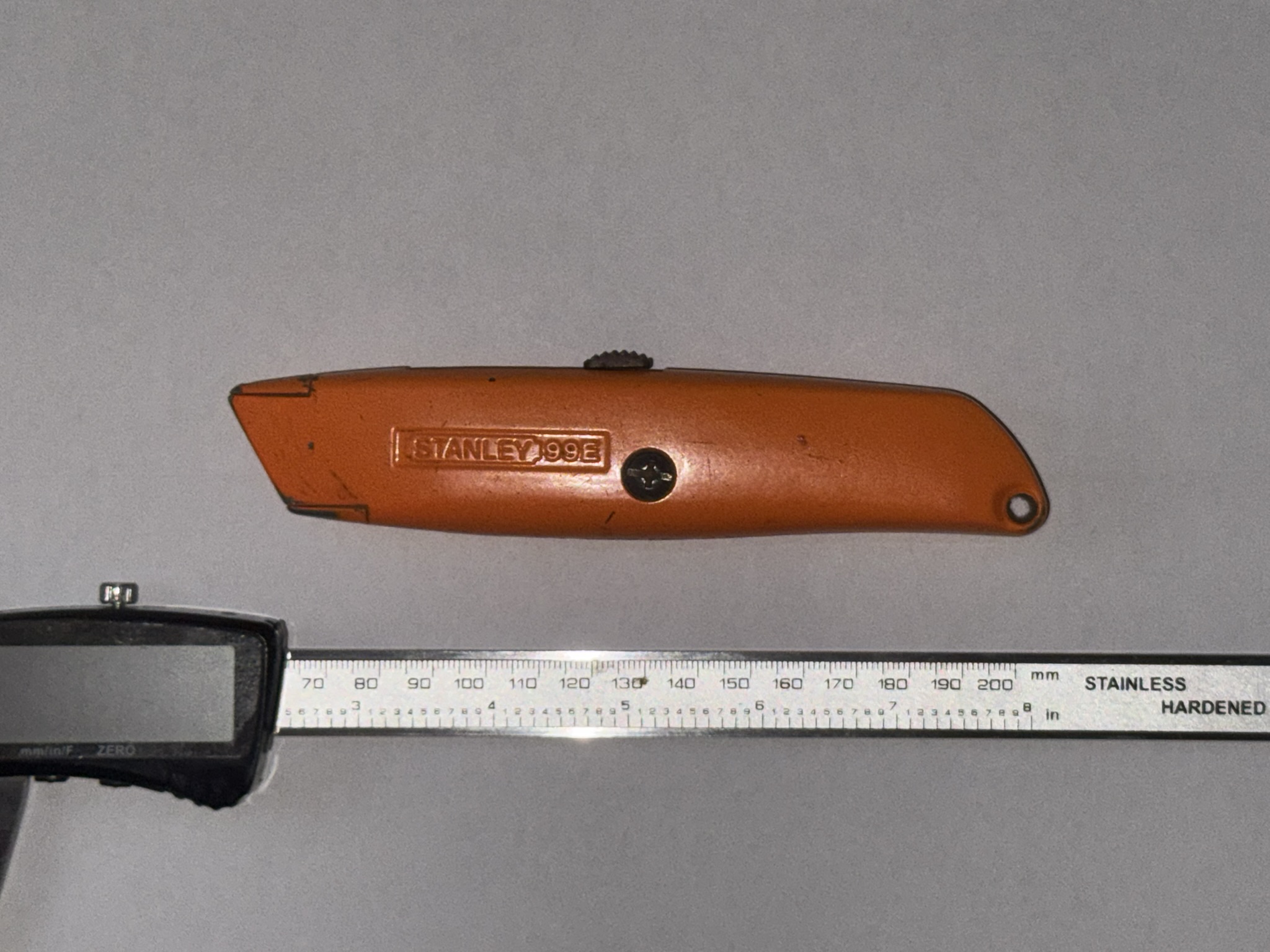
Example Taking image with phone
Image taken with iPhone, using calipers for scale
Step 2. Import into Inkscape
- Download and install Inkscape
- Open the photo.
Step 3. Set the scale of the drawing
- Using image from scanner
- Import the scan into Inkscape.
- Set the image’s real scale using that DPI noted above (Inkscape often auto-detects it).
- The SVG is to real-world scale (e.g., 1 mm = 1 mm).
- Using photo from camera
- Measure a known length of the reference object in Inkscape using the ruler or dimension tools.
- Compute the scaling factor
\text{scale factor} = \frac{\text{real size}}{\text{measured size in Inkscape}} - Apply that factor to the entire drawing (
Object → Transform → Scale).
Example settings scale
Using the calipers, measured 70 → 200 for a distance of 130mm. On screen measurement was 94.18mm. This gives are scale of 1.38(1.38 = 130/94.18).
Step 4. Trace the shape
- Trace or outline the shape using
Path → Trace Bitmapor manual Bézier tools. - user the
Detection modethat best outlines the shape. - Apply the trace.
- Clean up the trace removing anything that is not needed, including the reference object and any
Step 5. Export to file
- In Inkscape select the path that was created
- Open the export dialog
File → Export - in the Export dialog select:
- The
Customtab - Ensure the DPI is 96 (or note the value for use in OpenSCAD)
- Enable
Export Selected only - Change export type to
Plane SVG (.svg) - Clieck Export
- The
Step 5. Inport svg in to Gridfinity
- Open Gridfinity Custom Cutout
- Online using Makerword
- locally using OpenSCAD
- Upload the saved SVG
- Set the DPI if its not 96
- OpenSCAD treats SVG units as millimetres by default (assuming your Inkscape file uses mm).
- Adjust the bin size to suit
- Generate the cutout sample
- This generates a minimal print for testing the fit.
- Adjust using padding a depth as needed.
- Once happy generate the Gridfinity bin.